SC Quick Start Tutorial
Spatial Conformetrics calculates the overlap between a plan volume and a survey volume. The resulting charts and tables provide visual communication and a simple scoring system for conversations around business improvement.
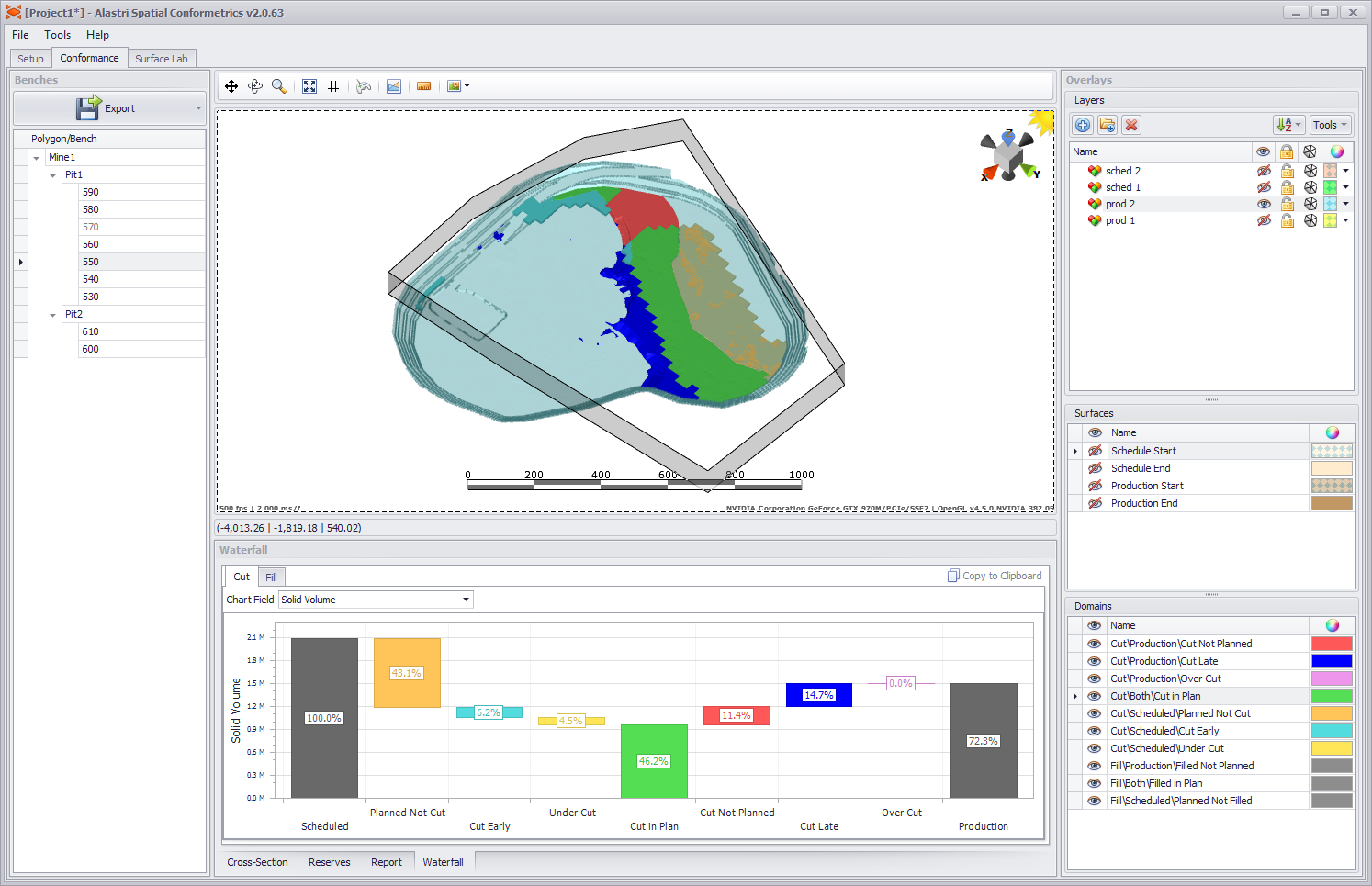
Spatial Conformetrics conformance view.
Spatial Conformetrics is organised into three tabs:
- Surface Lab may be used to create composite surfaces and triangulations.
- Setup contains an ordered task list to prepare the project.
- Conformance presents a 3D reporting environment to assess results.
The exercises in this chapter are for familiarisation purposes and are deliberately light on detail. More in-depth discussion follows in the next sections.
Unless otherwise noted, each exercise follows from the preceding exercise.
Contents
Setup
The setup tab contains an ordered task list to setup the project.
Settings
In Setup > Settings, toggle 'Use Block Model' to true.
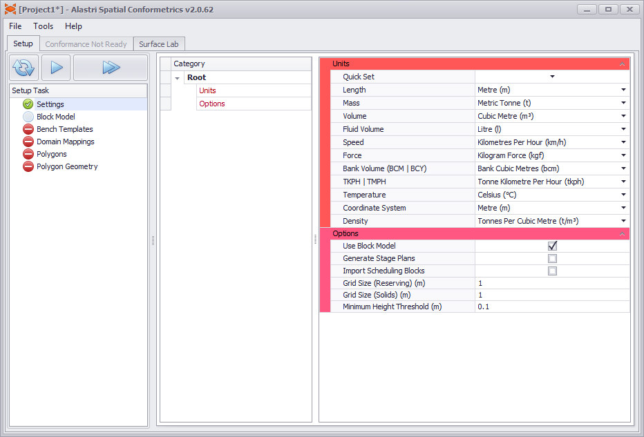
Settings > Use Block Model.
For this tutorial, leave all other settings at the default values.
Block Model
Load block models in the Block Model step.
![]()
Default block model step.
Quick notes:
- A reserve model is a collection of block models.
- Each project loads a single .resmodel file at a time.
- The New and Open buttons create and load reserve model files.
- The Edit button is where block models may be added or removed from the reserve model.
Create a Reserve Model
Press the New button to open the Reserve Model Generator.
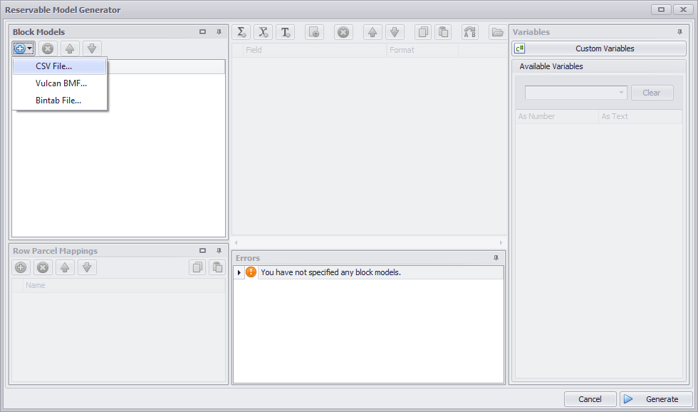
Reserve Model Generator > Import CSV file
Select import  > CSV file > bm1.csv
- Set the green Header Line to match the header text.
- Set the yellow Data Offset to match the first row of data.
- Press OK to finish.
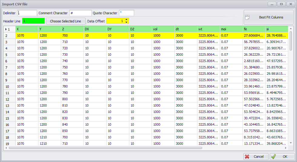
Block Model CSV preview dialog
When the block model is loaded, its header fields are listed in the Variables panel on the right.
- Drag and drop the variables to the appropriate field (or double click to map to the selected field).
- Numeric fields use the N("field") syntax, and text fields use the T("field") syntax.
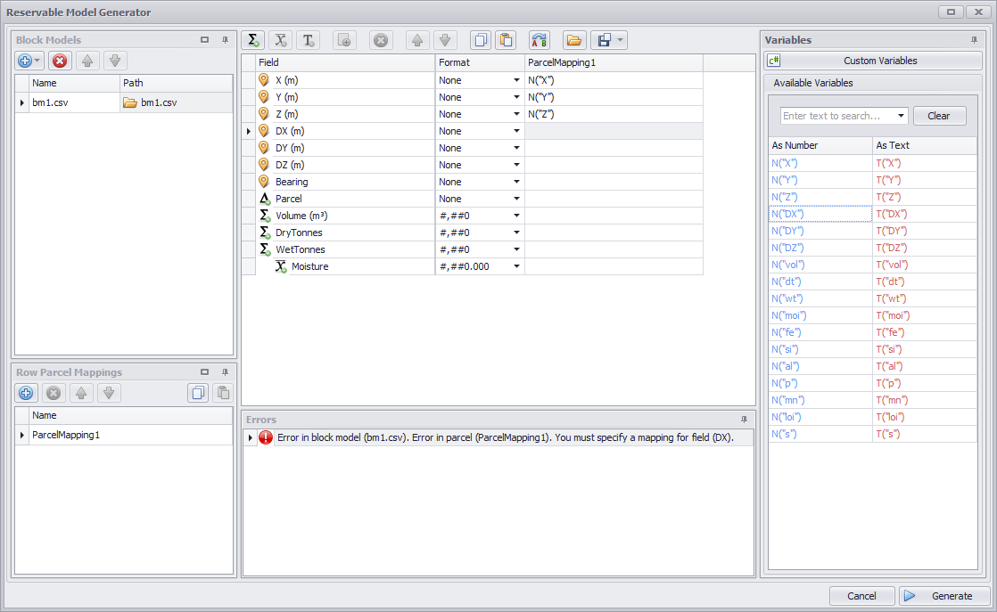
Map the block model values into the reserve.
New reserve fields can be created by clicking the sum  , weighted
  , and class
  icons in the top button ribbon.These add new rows into the field list.
- Sum fields are summed together, such as volume, tonnes and gold ounces.
- Weighted fields are weight-averaged by a sum field, such as iron percent or gold ppm.
- Class fields create subtotals of a sum field, such as Indicated / Inferred / Measured.
Create and map the fields for Fe, Al, Si, P, Mn, LOI, and S.
- Use the top button ribbon to add the fields under the correct parent.
- Use the variables list to map values into the fields.
- Select the appropriate format for each field.
- Check for hints in the Errors panel below the fields.
The Parcel field is used to categorise the material type in each block model cell.
- Most block models contain a material type field, such as "MatType" or "IDProduct'.
- If there is no material type field in the block model, see the Block Model Formulas section to write your own.
- Be careful to use the text T("material") syntax so that the parcel is read as text, not as a number.
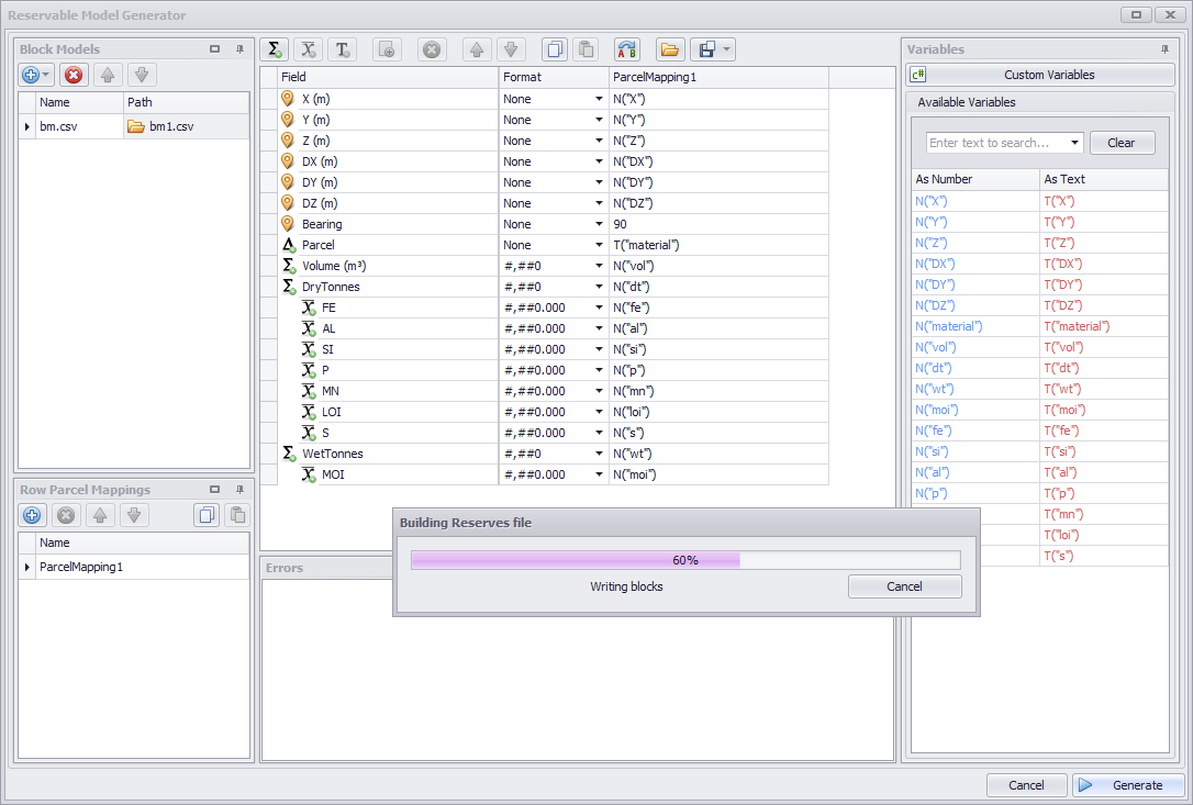
Once all fields are mapped as shown, press the Generate button to build the reserve model.
If the Errors panel is blank, and once all fields are mapped, press Generate to build the reserve model.
A Spatial Conformetrics project needs a valid link to the reserve model file in order to calculate reserves.
As such, a good rule of thumb is to save the reserve model file in the same folder as the Spatial Conformetrics project, to reduce confusion when sharing or backing up files.
Once the reserve model file has been generated, a block model summary is displayed for each loaded block model.
- Use the Min/Max toggle to inspect the data for missing or rubbish values.
- Check the material types, tonnes and grades for ballpark accuracy.
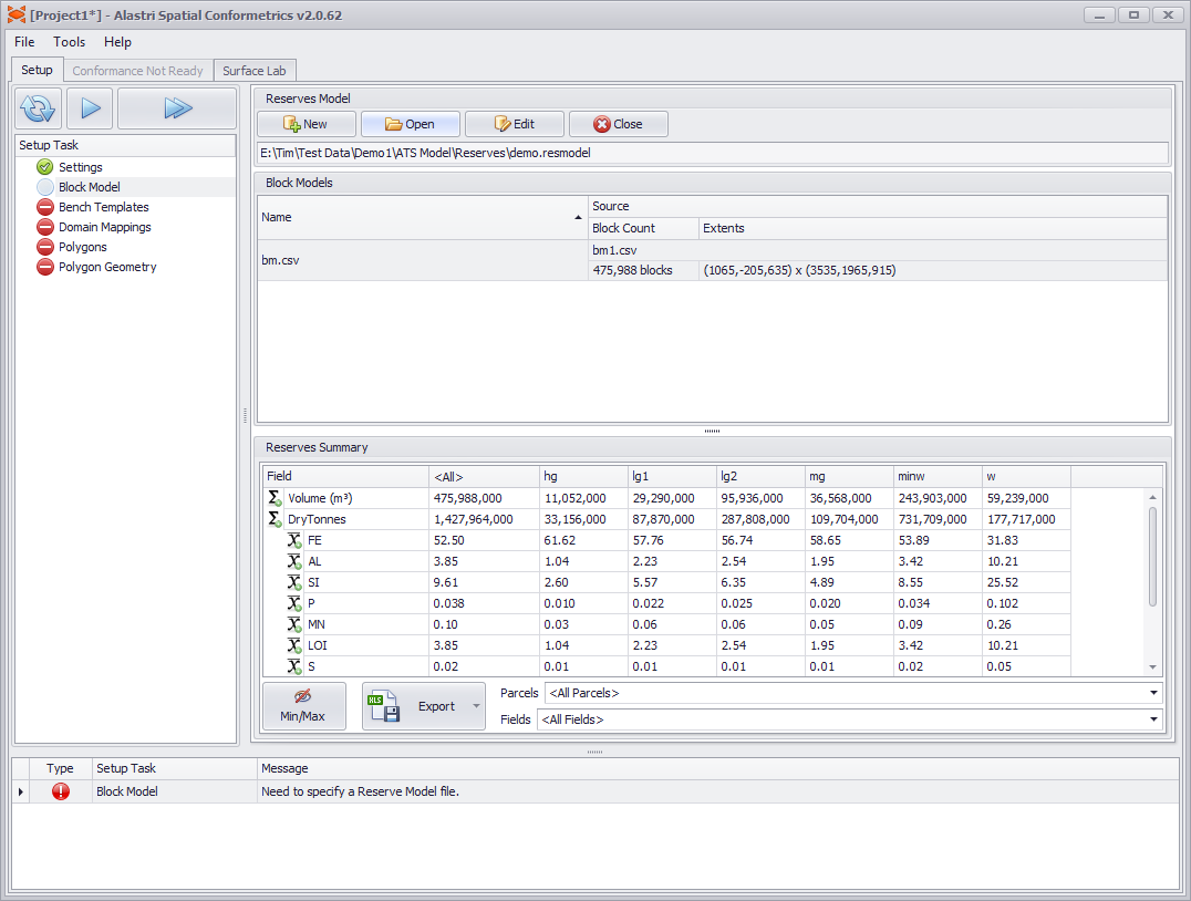
Use the block model summary table to inspect the data before continuing.
Once you are satisfied, press play to the next step.
Bench Templates
Set bench height options in the Bench Templates step.
![]()
Default Bench Templates step.
Create a Bench Template
- Select the blue plus icon > 'By Heights'.
- Set the template name to '10m'.
- Set the bench height to 10.
Optionally use the 'Add to Top' / 'Add to Bottom' to set different bench heights at different elevations.
Domain Mappings
To generate conformance solids, the software calculates the intersection of a production solid and a schedule solid, then cookie-cuts the results by the boundary polygon of each solid. The resulting volumes are referred to as conformance domains.
- Any intersecting volume is "mined in plan".
- Any production volume outside the schedule boundary is "mined not planned".
- Any schedule volume outside the production boundary is "planned not mined".
- Any production volume above or below a schedule solid is "mined late" or "over dig".
- Any schedule volume above or below a production solid is "mined early" or "under dig".
Different organisations may choose to report these volumes in different buckets, or with different names. The Domain Mappings step allows any conformance domain to be given a reporting name and colour to match company standards.
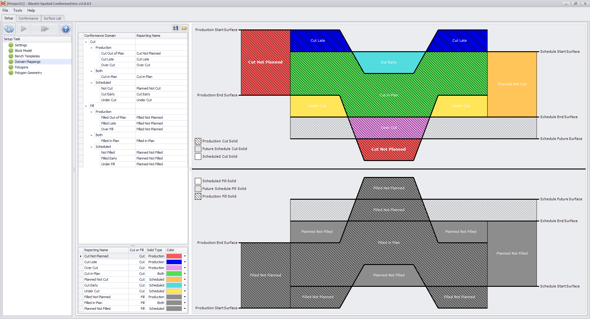
Domain Mappings are displayed on the cross-section diagram.
Polygons
Set the bench heights, block model, and containing surfaces for each reporting region.
Polygon 1
- Press the blue plus icon to add a new polygon.
- Rename the polygon to "Mine1/Pit1".
- Populate the polygon properties in the Properties panel:
- Select the appropriate Bench Template for pit1.
- Select the appropriate Block Model for pit1.
- Select the Production Start and Production End survey surfaces.
- Select the Schedule Start and Schedule End schedule surfaces.
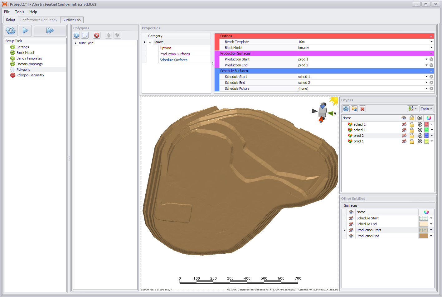
Polygon 1 properties.
Polygon 2
- Press the white copy icon
 to duplicate the last polygon.
 - Rename the new polygon to "Mine1/Pit2".
- Optionally change the polygon properties to match pit2 (for example, use a different production survey surface).
Once you are satisfied, press play to the next step.
Polygon Geometry
Draw the regional extents for each polygon.
- Select a polygon from the Polygons list.
- Use the polygon tool
 to delineate the selected pit area.
 - Repeat for all polygons.
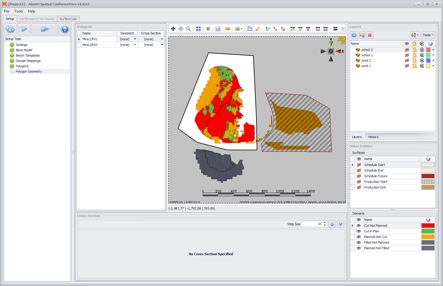
Draw the regional extents for each listed polygon.
Once you are satisfied, press play to finish the setup.
Conformance
Review site conformance in the Conformance tab.
- Benches panel (left): shows the highlighted pit or bench.
- Domain legend (right): shows the colour-coding for each conformance type.
- Viewport (centre): shows the 3D conformance solids.
- Reports (bottom): show charts, scores and reserves for the highlighted pit or bench.
Conformance tab overview.
Navigation
Use these tools to see and interact with the 3D design area.
Mouse Controls
Pan |  | Middle click and drag. |
|---|---|---|
Rotate |  | Right click and drag. |
| Zoom |  | Scroll wheel. |
Zoom Extents |  | Left click on the compass widget. |
| Vertical Exaggeration | - | Ctrl + Scroll wheel. |
Compass
The compass widget sits in the top right of the viewport.
| Plan View |  | Click on the axis cones to snap to orthogonal views. |
|---|---|---|
| Zoom Extents | Click on the grey cube to zoom to extents. | |
| Night Mode | Click on the sun icon to toggle night mode. |
Level Tree
The level tree displays the hierarchy of pits, stages and benches as defined by the polygon name and bench template.
| View Level | Left Click |
|---|---|
| Zoom to Data | Double Click |
| View Multiple | Control Click |
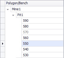
Click in the level tree to see the solid collection.
Measurement
Use the scale bar to estimate distances and scale in the viewport.
Viewport scale bar.
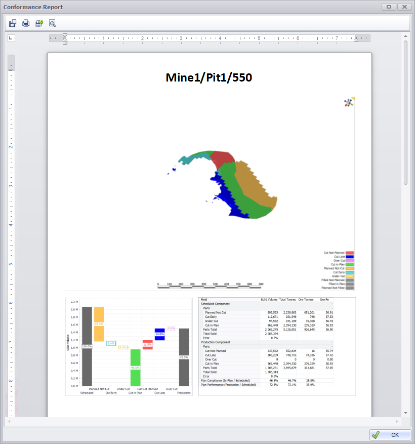
Charts
Click in the Waterfalls panel to see the conformance charts.
- The left "Scheduled" component is always 100%.
- The right "Production" component is the ratio of (Mined / Scheduled).
- The subtotals of each "Scheduled" and "Production" component are shown in the waterfall from left to right.
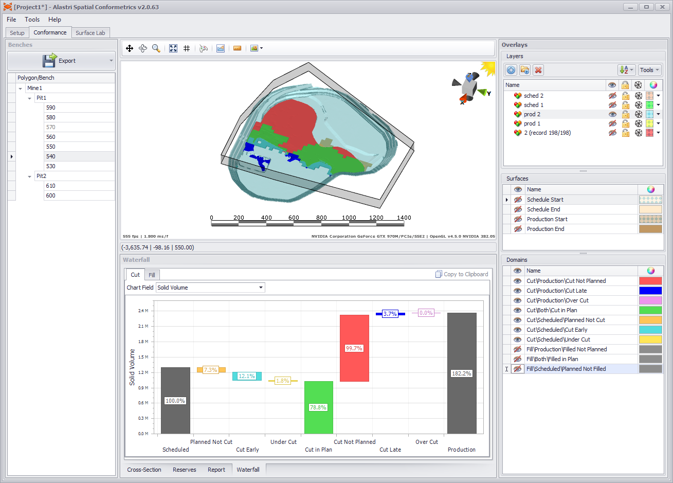
Conformance chart for Pit1 540RL.
Reports
Click in the Report panel to see the conformance scores.
- The Scheduled Component shows the subtotals of all scheduled volumes (mined and unmined).
- The Production Component shows the subtotals of all mined volumes (planned and unplanned).
- Plan Compliance is the ratio of (Mined In Plan / Scheduled)
- Plan Performance is the ratio of (Mined Total / Scheduled)
For example, the mine may move 150% of plan volume, but with only 75% conformance to the scheduled locations.
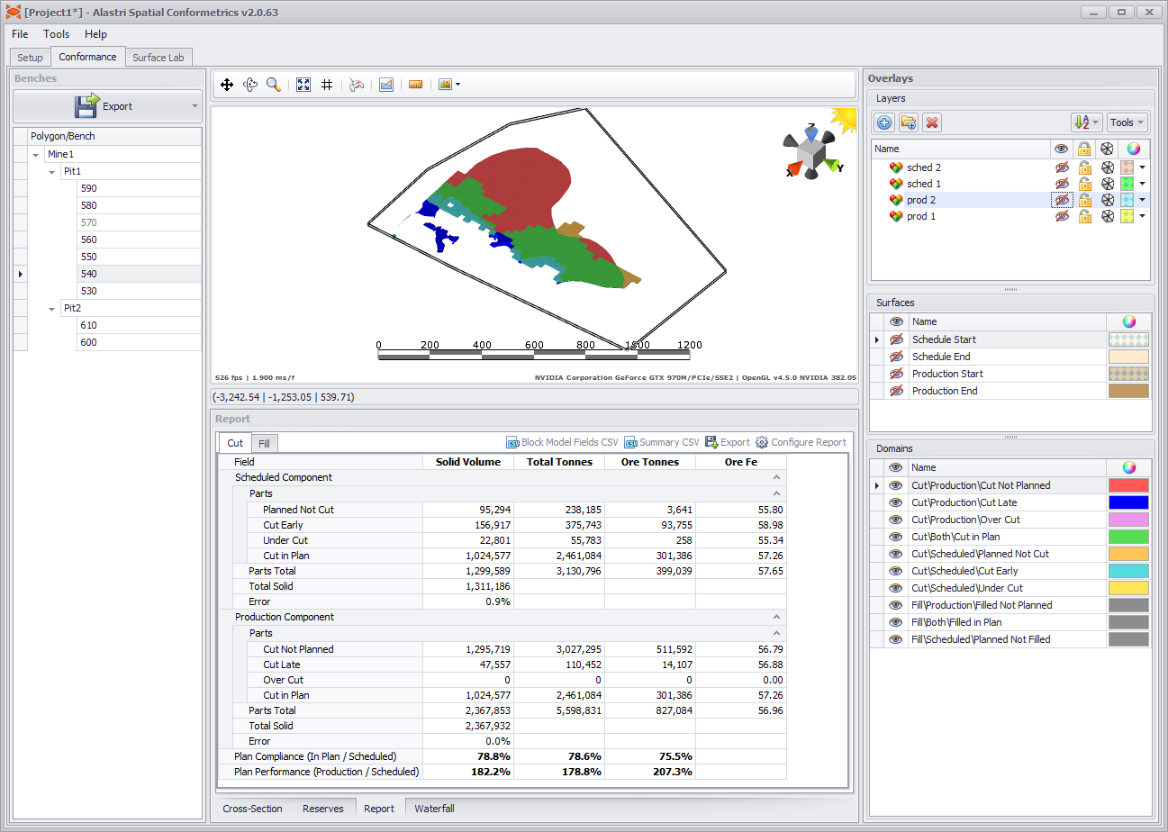
Conformance report for Pit1 540RL.
Conformance reports may be customised by clicking the 'Configure Report' button in the top right of the panel.
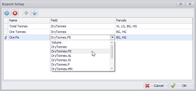
Conformance report custom layout.
The settings in Setup > Settings > Options may cause greater or lesser degrees of accuracy in the solid calculations.
Each scheduled component in the Reports table contains an Error row. The greater the error, the lower the accuracy of the result.
Aim to keep Error values lower than 1%. This can be achieved with tighter reserving grid sizes, and lower minimum height thresholds.
Reserves
Click in the Reserves panel to compare the planned and scheduled reserves.
- Use the tickboxes to show and hide reserves for different components.
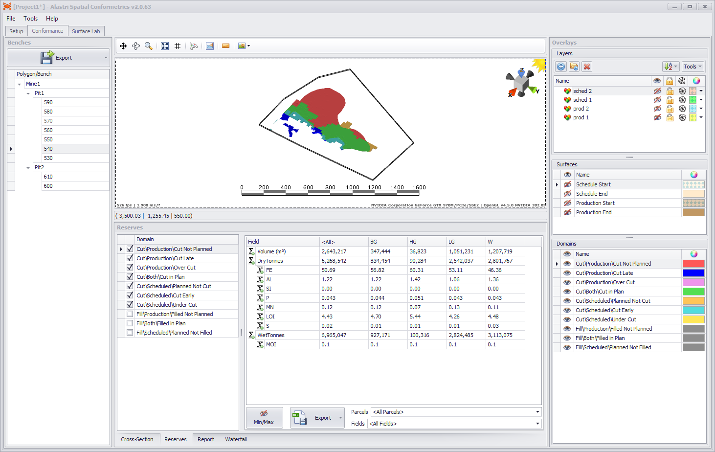
Reserves for Pit1 540RL.
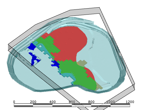
Cross-Sections
Click in the Cross-Section panel to view cut-aways of the conformance solids.
- Press the cross-section icon
 to begin.
 - Click and drag on screen to define the breadth and bearing of the section plane.
- Zoom, pan and vertically exaggerate the view inside the Cross-Section panel.
- Step forward and backward with the up/down arrow icons in the Cross-Section panel.
Cross section of Pit1 540-560 RL.
Export
In the top left of the application, select Export > Export Word Document.
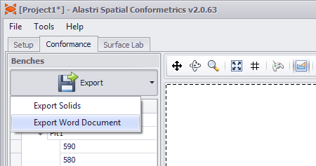
Export options.
In the dialog that opens, tick the benches to add to the report.
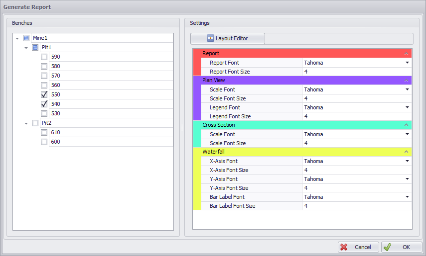
Select benches to export.
Click the Layout Editor button to open a reporting template.
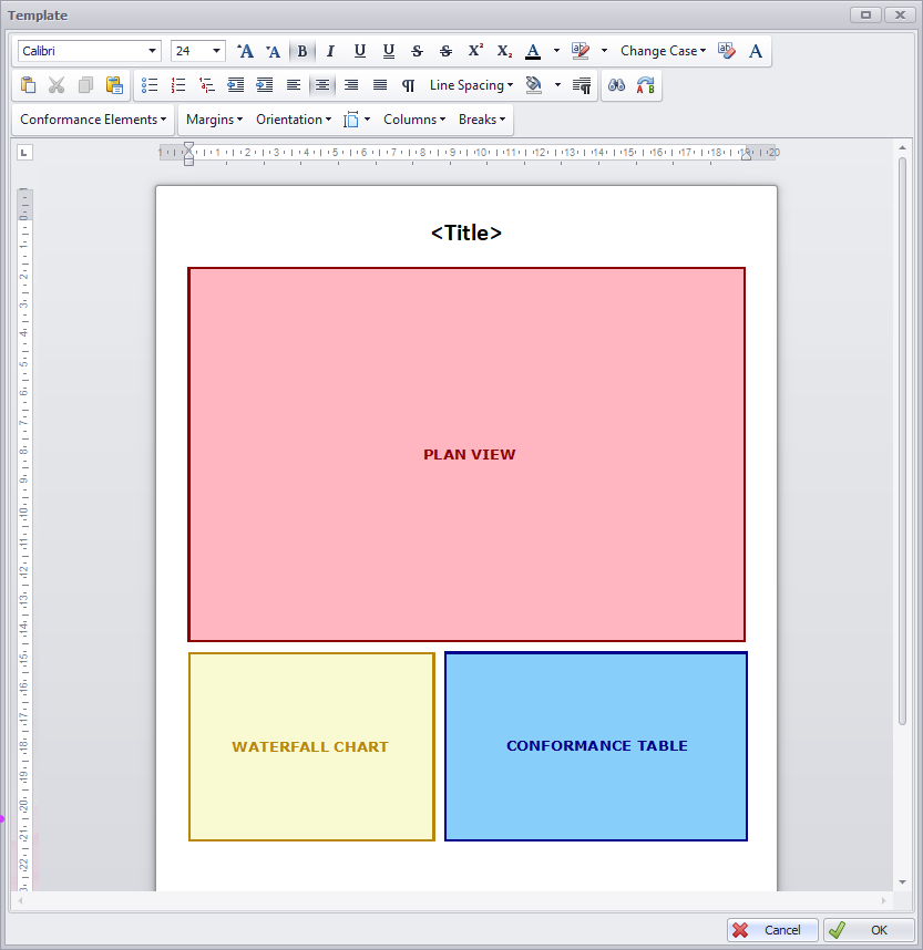
Drag and resize the elements to configure the report.
Press OK to accept and generate the report.
Review the generated report.
Press the save icon  to save as Microsoft Word document.